Mark Bomberg and Thomas Thorsell
1. Background
The following paper discusses an integrated testing and modeling of hygrothermal performance of building enclosures. To this end one must address three separate objectives:
-
Develop a method to determine the effect of air flow on thermal performance of the wall assembly under reference pressure conditions and quantified volume of air on ingress and egress
-
Develop a method to characterize the effect of air flow on thermal performance of the wall assembly as built
-
Develop information suitable for verification of HAM models for a given assembly under reference conditions that involve simultaneous ingress of air and moisture transfer.
The methodology presented here involves measuring local heat fluxes and using HAM models[1] to generalize the results. To address the validity of results calculated from the model, the latter is verified during the first stage of testing by comparing with the measured effects of multi-directional transfer (Kosny et al 2007). Verification of moisture transport calculations has been addressed elsewhere (Bomberg et al 2006, Pazera, 2007) so the only area in which HAM models are not verified is that of air flows. For this reason the proposed methodology includes a combination of air flow with wetting and drying of the wall system.
2. Application of this methodology to non-residential walls
Thorsell and Bomberg (2008) discussed two non-residential walls. This paper presents non-residential walls. One of them, called a multi-component (MC) wall was built with glass fiber insulation in a metal stud system. It was provided with a vapor retarder (VR) on the interior and air barrier (AB) that also functioned as a water resistive barrier (WRB) on the exterior of the wall. The second wall was an exterior panel system (PS). The panel joints on the long sides of the panels have thermal breaks placed between the metal facers and a factory formed male-female joinery in which a non-skinning high grade butyl sealant is placed. The panel is attached to a system of vertical steel studs. During panel installation, a butyl sealant is applied between the supports and the panel liner element at the panel ends. This seal is, in turn, connected to the shop applied butyl so that each panel has a network of butyl seals surrounding its perimeter. This type of sealing technique provides the durable air and vapor control on the liner side of the panel and is applicable to different climates.

Figure 1: Multi-component (MC) wall system (top), and exterior panel system (PS, bottom)
The differences between these two walls are in two areas:
-
Continuity of moisture control - The vapor retarder is most likely disrupted by electrical outlets and structural brackets or floor edge detailing.
-
Thermal efficiency. PS is efficient because a great effort is made to maintain the continuity of the insulation. Conversely, MC has continuity of insulation layer disrupted by presence of metal studs every 16 or 24 inch.
3. Results of 2-D Model Calculations
In contrast with part 1 where the calculations were used to analyze the measured data, we will start with calculations to highlight the differences between metal and wood frame walls.
An average R-value of MC wall depends on its orientation calculated with 2-D software for vertical cross sections R = 3.33 (m2K)/W and for horizontal cross section R = 1.83 (m2K)/W. Observe that the average of both is 2.58 (m2K)/W.
Figure 2 shows also the result of calculation for horizontal cross-section where the lowest temperature on the interior surface is 11.3 oC.

Figure 2: Results from 2-D model calculation for horizontal cross-section in MC wall system
On the other hand, similar calculations for PS wall show small differences, namely 2.40 (m2K)/W and 2.36 (m2K)/W. Yet, as shown in Figure 3, for PS wall significant differences are caused by the wall construction details. If the steel frame wall is capped with a simple C-profile or this profile is in line with the panel joint, the effect on 3 joint panels is as large as 0.33 (m2K)/W or 1.9 (ft2hroF) /BTU.

Figure 3: Results from 2-D model calculation for vertical cross-section in PS wall.
In view of such an impact we needed to establish errors caused by a flanking loss to the stainless chamber - designed for VOC emissions (Figure 4)
For SP wall where both metal layers were placed on the cold side of the bottom runner and contacting the floor through the air sealant the heat loss is unusually high. Similar correction for MC wall is small because only one part of the runner track and metal layer was exposed to the cold chamber, while the other part of the runner truck was exposed to room temperature.

Figure 4: caused by the flanking loss to the stainless steel chamber (VOC testing chamber) for SP wall is 26.3% in this analyzed test.
4. Results of Measurements
4.1. Thermal resistance
For MC wall, calculations yields an average heat flux of 13.6 W/m2 with a corresponding temperature difference of 43.5oC, giving the apparent R-value of 3.20 (m2K)/W. The clear-wall R-value for the wall is 2.59 (m2K)/W that can be compared with the mean value in computer calculations 2.58 (m2K)/W.
The R-value was reduced to 2.16 (m2K)/W in during the step 2, when 50 Pa air pressure was applied i.e., the effect of air infiltration was determined as 15.6 %.
For PS wall the measured clear wall R-value was 1.78 (m2K)/W. This can be compared with 2.4x0.737 = 1.75 (m2K)/W. The R-value was reduced to 1.64 (m2K)/W in during the step 2, when 50 Pa air pressure was applied i.e., the effect of air infiltration was determined as 8 %.
The MC wall shows the energy equivalent R-value of 2.16 (m2K)/W, or 12.3 (ft2 hr oF) / BTU. Comparing with the nominal R-value in the cross-section through thermal insulation of 4.05 (m2K)/W or R23 (ft2 hr oF)/BTU one may establish energy efficiency of this wall equal to 53.3%.
The PS wall has the nominal R=2.75 (m2K)/W or 15.6 (ft2 hr oF) / BTU. The measured energy equivalent R-value was 1.64 m2K)/W but when correcting for the errors caused by the flanking loss it is actually 2.4x0.92= 2.21 (m2K)/W or 12.5 (ft2 hr oF) / BTU. This wall shows energy efficiency of 80.1%. This clearly shows superiority of external insulation placement if the structural support is made of highly conductive medium.
4.2 Measurements of temperature profiles
The temperature distribution on the surface of the gypsum board (underneath the CBL) is shown in Figure 5 for the PS and Figure 6 for the MC.

Figure 5: Temperature on the surface of gypsum board (underneath the CBL) on the PS wall.

Figure 6: Temperature distribution on the surface of the gypsum of the MC wall.
Figures 5 and 6 show the effect of thermal bridge created by the metal stud and this effect is much larger for the MC than PS walls. Let us now compare temperature distributions measured on the wall without CBL during step 1 without (graph a) and 2 (with air pressure, graph b). Figure 7 shows top and Figure 8 middle position. Orange curve represent PS and blue represent MC wall.
The conclusion is self evident. Air infiltration affects the temperature profiles in the PS wall to a much smaller extent than it does in MC wall. Not only the temperature on the surface is much higher (for both walls) but the surface temperature increases with growing distance from the stud.

Figure 7: Top of the wall, temperature on wall surface without (a) and with air pressure (b)
Figures 7 and 8 clearly show that the effect of air movement in the porous insulation of MC wall is higher than that in the empty air cavity behind the thermal insulating panel. Observe that the MC wall was built with the standard air and vapor barrier protections.

Figure 8: Temperature on wall surface (middle) level, without (a) and with air pressure (b)
4.3 Effect of convection barriers
To examine if air movement was combined with a natural convection in the large open air space of PS wall, one cavity was provided with convection barriers as shown in Figure 9 and the measured temperature distribution is shown in Figure 10.

Figure 9: Three convection barriers were mounted in one cavity to compare its thermal performance with the open one.

Figure 10: Temperature distribution for cavity without “x” and with “o” the convection barriers (marked “- . –“ ) measured on the inner wall surface. The panel joints are also indicated (“- -“).
Figure 10 shows that provision of convection barriers did not suppress the convection effect, perhaps even increased its impact. Let us now compare the nominal thermal resistance i.e., measured in the center of thermal insulation. In one section we obtain the average heat flux 17.8 W/m2 and temperature difference of 41.43 oC giving the apparent R-value of 2.33 m2K/W while in the other one the corresponding values are heat flux 17.23 W/m2 and temperature difference of 42.9 oC giving the apparent R-value of 2.49 m2K/W. Subtracting R-value of 0.61 m2K/W of the CBL we obtain thermal resistances of 1.72 m2K/W and 1.88 m2K/W. It appears that convection is involved in these measurements.
4.4 Moisture performance of these walls
For ease of measurements a rectangular cut was made in the drywall and after placing sensors (RH, T, air pressure taps) was back sealed in place. The same approach was used for air flow controlling plates that were made out of transparent plastic. (These openings could closed or open as needed).
As shown in Figures 7 and 8 there is connectivity between the cavities of both walls and the ambient air and since the temperature in the cavity is increased to the level of room temperature, one may assume substantial influx of the room air. To check this assumption computer cooling fans extracting about 1 cfm of air under about 10 Pa pressure difference were installed on each wall.
In cold and dry climate the fan action caused a slow but continuous increase in RH but when hot and humid climate was applied the reaction was rapid. Condensation was immediately observed on the MC wall, and none on the PS wall. Figure 11 show the water condensation on the Plexiglas plate.
Observe that presence of thermal insulation creates a temperature difference that in the moment of reverse thermal gradient delivers moisture to the inner side. Since the air temperature in the air gap is practically the same, there was no visible condensation. Figure 12 show mold growth on the drywall plate observed at the end of the test.

Figure 11: Condensation caused by reverse thermal gradient.

Figure 12: Mold growth observed on the inner side of drywall in MC wall assembly
Concluding Remarks
This paper, written in two parts to address differences between wood-frame and metal frame walls, applies a new integrated testing and modeling methodology (Bomberg and Thorsell, 2008; Thorsell and Bomberg, 2008).
Introduction of such a methodology is necessary for several reasons:
-
With reduction of heating and cooling loads the optimization of the building enclosure becomes more difficult without access to adequate tools.
-
Use of advanced heat, air and moisture models is necessary to address the effects of climate and moisture movement on thermal performance.
-
HAM models must be verified on the level of material characterization (Bomberg et al 2006) and on the level of assembly (Bomberg and Thorsell, 2008)
-
With increased air tightness of building enclosure the local air leakage becomes more significant for assessment of durability and indoor air quality, which includes pollutants, VOC, mold spores etc.
-
Moisture carried by air and moisture redistribution as it may be accelerated by air movements need to be assessed and again this requires a combination of testing and modeling
-
HAM modeling needs to be linked with the traditional energy evaluation codes to permit introduction of the “predicted” field performance t the estimated energy use
-
HAM modeling needs to become the basis for a durability evaluation, as durability is the key consideration for designing sustainable buildings.
-
Yet, as shown in case of PS wall, small changes in design of the details of highly conductive materials such as metal walls, wall-window interfaces etc may lead to large differences in their hygrothermal performance i.e., condensation potential and thermal performance. Therefore, testing must be used to support modeling.
-
This paper identified areas where current HAM models are not developed enough to address critical issues of design and postulated testing procedures to that when carefully followed may assist verification of HAM models.
There is an interesting question – what can we do realizing that our HAM modeling capability stops short of the required needs (Lstiburek et al 2000, 2002, Onysko, 2002). Today, we can rely on model heat transfer calculations, moisture transfer in porous materials (if the material characteristics are verified) but air / moisture interaction is either poorly addressed or non-existing.
The design team of Olympic village for 2010 in Vancouver, Canada (mixed climate) showed the way, how to avoid the risky design (see Figure 13).
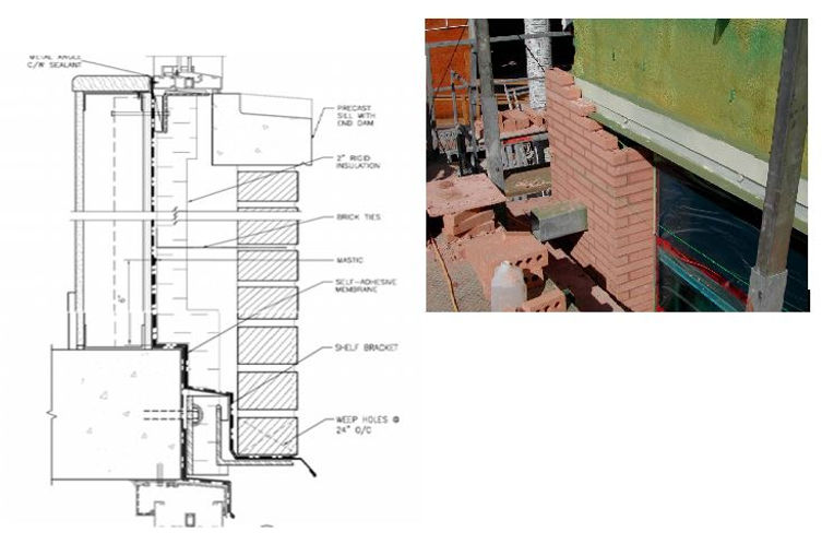
Figure 13: All insulation (R7 (m2K)/W is outside of the steel studs (see Fookes, 2008)
Appendix A: Definitions
Terms used in this paper are defined here:
-
R-value in this paper represents air to air resistance to heat flow. It is an inverse of the U-value. Note that this definition is different from that used in ASHRAE. This definition permits us to avoid several measurements on the wall surface to establish an average surface temperature when multi-dimensional heat transfer causes large local differences.
-
Apparent R-value = a ratio between temperature difference between indoor and outdoor air to the local heat flux measured at the local point without subtracting the resistance of calibrated boundary layer (CBL).
-
Local R-value = a ratio between temperature difference between indoor and outdoor air to the local heat flux measured at the local point when the resistance of calibrated boundary layer (CBL) is subtracted.
-
Nominal R-value = thermal resistance under steady-state, unidirectional heat flow through the center section of the insulation i.e. in the symmetry point between thermal bridges. R-values measured under standard conditions (step 1) are considered as the reference.
-
Clear-wall R-value = the ratio between average temperature difference between indoor and outdoor air to the mean value of the heat flux across the whole wall. This would be R-value measured with a calibrated hot box or calculated for the central area of the wall (without consideration to increased heat flow on the wall perimeter, corners etc)
-
Energy equivalent R-value = the clear-wall R-value in which the difference between reference R-value and those measured under specified effects of air and moisture flows are incorporated.
REFERENCES
Bomberg, M., Pazera, M. and Zhang, J., 2006, On Validation of Hygric Characteristics for Heat, Air and Moisture Models, 3rd Int. Conf. on Building Physics, Montreal.
Bomberg M. and Thorsell T, 2008, Integrated Methodology for Evaluation of Energy Performance of the Building Enclosures, J. Bldg Phys vol. 32, July 2008
Fookes D, A 2010 Olympic village perspective, BECOR Seminar May 20, 2008 – Building Enclosure Council Ottawa Region
Kosny, J., Yarbrough, D., Childs, P., and Syed, A., 2007, "How the Same Wall Can Have Several Different R-Values in proceedings of ASHRAE THERM X, Clearwater, FL, Dec.
Ojanen, T.R. and Kumaran, M.K. (1996). Effect of Exfiltration on Hygrothermal Behaviour of a Residential Wall Assembly, J. Thermal Envs. and Bldg. Envs., 19: 215–228.
Thorsell T and Bomberg M., 2008, Integrated Methodology for Evaluation of Energy Performance of the Building Enclosures, J. Bldg Phys vol. 32, July 2008
Pazera M., 2007, Model Based Characterization of Construction Materials for Hygrothermal Performance Evaluation. PhD Thesis, Syracuse University, 2007.
Lstiburek J. W, K. Pressnail and J. Timusk, 2000, Transient Interaction of Buildings with HVAC Systems – Updating the state of the art, J. Thermal Env. and Building Science, 24: 111-131
Lstiburek J.W, K. Pressnail and J. Timusk, 2002, Evaluating the Air Pressure Response of Multizonal Buildings, J. Thermal Env. and Building Science, 25: 299-320
Onysko D.M, 2002 Air Tightness of Joints in Wall Sheathing as a Function of Lumber Drying, ICBEST conference in Ottawa
[1] Calculations of heat transfer though porous materials without consideration of moisture is an approximation because phase changes of moisture affect the temperature and the change in temperature affects the relative humidity in materials